 Screen Shots! Beauty, eh?
Last update: 2003/04/24
Back to Main
Page
How a Backer works
A Backer ``draws'' the data being saved by turning each bit of the data
stream, 0 or 1, into a horizontal black or white dash in its video
output. In high density mode there are 80 of these dashes across each
line of video and in low density mode there are 32. Each video line
also begins with 8 additional dashes in the pattern 01000101, equivalent to the byte 0x45. These additional bits are added by the
Backer hardware during data output and are automatically stripped from the
signal during data retrieval.
Here is an example of one line of video from the Backer's low density
mode.
|
|
|
|
|
|
|
|
|
|
|
|
|
|
|
|
|
|
|
|
|
|
|
|
|
|
|
|
|
|
|
|
|
|
|
|
|
|
|
|
|
| 0 | 1 | 0 | 0 | 0 | 1 | 0 | 1 | 0 | 0 | 1 | 1 | 0 | 0 | 1 | 1 | 0 | 0 | 1 | 1 | 0 | 0 | 1 | 1 | 1 | 1 | 1 | 0 | 0 | 0 | 1 | 0 | 1 | 1 | 1 | 0 | 0 | 0 | 1 | 0
|
| 0x45 | 0x33 | 0x33 | 0xE2 | 0xE2
|
Beneath the black and white dashes is shown the bit pattern they are
equivalent to and below that is shown how the bits are divided into
bytes. The bits are written and read in left-to-right order (the same
direction, of course, as a television's scanning). That's all there
is to a Backer: put it in ``transmit'' mode and send it the bytes you
want written to tape; put it in ``receive'' mode and read bytes from
tape.
Of course, turning this into a useful data storage and retrieval system
requires a lot more work on the software side. The first problem to
overcome is that Backer's do not retrieve a fixed number of bytes from each
video field, rather a Backer may skip over the first and/or last few
lines. On the one hand this means that one should not use these lines
for data storage and on the other hand means the read-out software needs to
be able to identify, asynchronously, the start and end of each video
field. Once a solution to this framing problem has been acheived, the
next obstacle to data storage and retrieval is tape noise. A VCR and
VHS tape is not a data-grade recording medium by any stretch of the
imagination so a fairly robust forward error-correcting code must be
applied to the data stream to allow its accurate recovery. Finally,
during playback Backers rely on the data stream being ``self clocking''
meaning that the Backer circuitry uses the black-white transitions in the
video signal to find the bits. If a long stretch of the line has no
transitions in it, the Backer circuitry can loose track of where it is and
stop reading out bytes. The solution is to introduce a run-length
limiting bit modulation technique to ensure a minimum transition
frequency. In practice, however, it proves effective to simply mix
the data being written to tape with noise from a simple random number
generator and this has the advantage of maximizing tape data
capacity. The software included in the linbacker driver package is capable of performing all
of the encoding and decoding tasks above.
What you see on your television
Stable 3.x Versions
These images are for NTSC video. Most televisions can't display
some number of the top and bottom lines of video so they won't actually be
visible on your set. These pictures were obtained by piping the
output of bkrencode into a program
I've written for analyzing tape data streams and then doing a screen
capture with the GIMP.
|
This first image is of a data sector (one video field) and it's not too
helpful unless you know what you're looking at. The same output can
be generated on your television by typing
cat /dev/zero >
/dev/backer/0/nhs
The version 3.x format is not as much of an improvement over 2.x as 2.x
was over 1.x but it is not without its merits. The error control code
is now used to only correct errors in actual data, it is not wasted
correcting errors in unused portions of the sector. Also, the key
bytes are spread more uniformly throughout the sector. This last
improvement combined with a new, more robust, algorithm for identifying the
key bytes means that it is practically impossible for noise to cause a
sector to be lost --- the software can accurately identify sectors even on
tapes which have been badly physically damaged.
|

|
|
This image is more informative. This is a sector from the
beginning of record (BOR) mark and it allows you to make out the structure
of the format. First, the vertical lines down the left side of the
image are not part of the tape data. They are produced by the Backer
hardware which prefixes each line of video with the byte 0x45. This
presumably provides the means by which the hardware's bit clock is
synchronized on playback. The top few lines contain the sector leader
which is just filled with 0xe2 and is used to pad out the first few,
unusable, lines of video. Likewise the bottom few lines contain the
sector trailer which also pads out unusable lines but with 0x33. The
key bytes can be seen scattered diagonally through the sector and are used
to identify the location of sectors in the data stream. The vertical
bars filling the bulk of the image are the filler bytes (0x33) used in BOR
and EOR sectors and would contain data if this were a normal data sector
(see above). The parity bytes for the error control code are at the
bottom, filling several lines immediately above the trailer. Finally
the sector header can be made out as four bytes, here all 0, appearing just
above the parity bytes towards the right side of the video frame.
|

|
|
Here's what a low density data sector looks like. You can get output
like this by typing
cat /dev/zero >
/dev/backer/0/nls
|

|
|
And here's a sector from the low density BOR mark.
|

|
bkrmonitor
Version 3.2
|
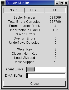
The image at right shows bkrmonitor after a 545 million byte recording that had
been made in EP mode was recovered from tape. As you can see, the raw
recording could not be recovered from tape completely error-free as there
were 108 uncorrectable data blocks. However, this recording was made
using the new bkrenhanced utility
which had no trouble filling in the lost sectors as can be seen from it's
output below.
bkrenhanced: DECODING at 92.2% efficiency
bkrenhanced: Number of lost sectors detected: 108 of 321045
bkrenhanced: Number of errors in worst block: 3 (20 allowed)
This shows that 108 sectors of the 321045 data sectors in the recording
needed to be corrected which is a mean error rate of about
3*10-4. We also see that no sector group required more
than 3 of its 255 sectors to be replaced. bkrenhanced's error control code can replace up to 20
sectors in each group so there appears to be plenty of headroom as one
would expect given the mean error rate and the code rate.
|
|


